Introduction to MIG Welding
MIG (Metal Inert Gas) welding, also known as GMAW (Gas Metal Arc Welding), is an arc welding process that uses a continuous solid wire electrode to join metal. An inert gas, like argon or a gas combination, shields the wire electrode and the welding station. An inert gas, like argon or a gas combination, shields the wire electrode and the welding station. In MIG welding, an electric arc forms between the base metal and the wire electrode. The arc melts the wire and base metal to form the weld pool. The wire electrode continuously feeds into the weld pool as the welder moves along the joint. This provides a steady flow of filler metal. The main component needed for MIG welding are Power supply: This provides current to maintain the arc and melt the wire electrode. Most MIG welders use a constant-voltage (CV) power source. wire feed unit: feeds the wire electrode at a steady, controlled rate into the weld pool. This allows the welder to adjust the wire feed speed. The MIG torch holds the wire electrode and directs shielding gas to the weld area through a nozzle. The welder holds the MIG torch handle and controls the welding process. Shielding gas supply: Provides an inert shielding gas like argon or a gas mixture around the arc and weld pool.
History of MIG Welding
MIG (metal inert gas) welding, also known as GMAW (gas metal arc welding), was invented in the 1940s. It emerged as an improvement over stick welding and quickly became popular in manufacturing industries. The first MIG welders used solid wire electrodes and carbon dioxide shielding gas. In 1948, Lyubavskii proposed using inert gases like argon and helium for shielding instead of carbon dioxide. This allowed the welding of non-ferrous metals like aluminum and magnesium. In the 1950s, consumable electrode MIG welding using a continuously fed electrode wire was developed. This improved the productivity, quality, and convenience of MIG welding. In the 1960s, the use of mixed inert gases like argon and carbon dioxide became common. This provided benefits like higher weld penetration and a lower cost compared to pure inert gases. In the 1970s, pulse MIG welding was introduced. Pulsing the welding current helped improve control and weld quality. Other advances were semi-automatic and automatic MIG welding systems for high-volume production.
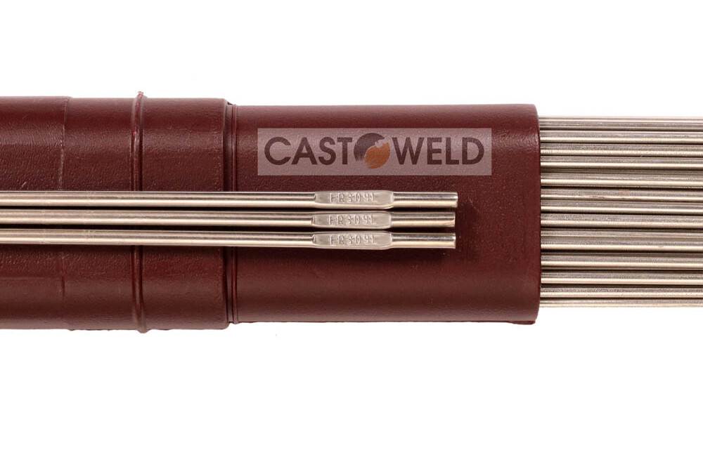
Types of MIG Wire
There are two main types of wire used in MIG welding: solid wire and flux-cored wire. Solid Wire A solid wire is a single strand of wire that does not contain a core. It requires shielding gas from an external cylinder to protect the weld pool from atmospheric contamination. The most common materials for solid MIG wire are steel, stainless steel, aluminum, and copper alloys. Solid wires can carry higher currents and allow for faster travel speeds than flux-cored wires.
Flux-Cored Wire
The flux-cored wire contains a core of fluxing agents inside the wire, which provides shielding for the weld. This eliminates the need for external shielding gas. Flux-cored wires are well suited for outdoor applications where wind can disrupt external shielding gases. Common types of flux-cored wire include gas-shielded and self-shielded. Gas-shielded flux-cored wires use additional gas to supplement the flux-core protection. Self-shielded flux-core wires provide full shielding from the flux alone. Differences Between Solid and Flux-Cored The main differences between MIG solid wire and flux-cored wire are:
Solid wire requires external shielding gas; flux-cored wire uses gas from the flux core.
Flux-cored wire can be used outdoors where wind disrupts external shielding gas.
Solid wires accommodate higher amperage and faster travel speeds.
Flux-cored wires allow welding in all positions, while solid wire is limited.
Solid wire produces very little slag and splatter compared to flux-cored wire.
Flux-cored wire creates higher-quality welds on dirty or rusty materials.
So in summary, solid MIG wire offers faster welding speed but needs external gas shielding. Flux-cored can weld in all positions without shielding gas but has slower speeds.
1. MIG Wire Materials
MIG welding can use a variety of wire materials, depending on the base metal and desired properties.
Mild Steel
The most common MIG wire is mild steel, which contains a low carbon content. It is inexpensive and versatile for welding most steel. Mild steel MIG wire provides good weld strength and is easy to use, even for beginners. It can weld materials up to 1/4 inch thick.
Stainless Steel
Stainless steel MIG wire is ideal for stainless steel materials as well as nickel alloys. It provides excellent corrosion resistance while maintaining strength. The two main types used are 308 and 316 alloys. Stainless MIG wire allows welding thinner materials around 1/8 inch thick. It produces smooth, clean welds.
Aluminum
Aluminum MIG wire is necessary for welding aluminum base metals. It contains silicon or magnesium to improve flow and wetting when molten. 4043 and 5356 are common aluminum alloys. Aluminum wire feeds smoothly and allows faster travel speeds. It’s used for welding thinner aluminum, like sheet metal or plates.
Other Materials
MIG wire also comes in alloy types like Inconel or Monel for specialized applications. There are copper-coated MIG wires to weld reactive metals like titanium. Nickel-based wires can weld high-temperature alloys. However, mild steel, stainless steel, and aluminum are by far the most common.
MIG Wire Sizes
The diameter of the MIG wire is measured in inches, or millimeters. Standard sizes range from 0.023 inch (0.6 mm) up to 0.045 inch (1.2 mm). The most common MIG wire sizes are 0.030 inch and 0.035 inch.
Choosing the optimal wire diameter depends on several factors:
Base Metal Thickness: Thicker metals require larger wire diameters to ensure sufficient penetration. As a general rule, match the wire diameter to the thickness of the metal or use wire that is 0.001-0.003 inches larger.
Welder Settings: Standard MIG welders work best with 0.030–0.045 inch wire. Smaller diameters may require higher voltage capabilities. Larger diameters need higher amperage capacities.
Joint Type: For fillet welds on T-joints, a smaller wire size can be used since full penetration is not required. Larger diameters are needed for full-penetration groove welds.
Welding Positions: Vertical and overhead welds require larger wire to prevent the weld puddle from dripping due to gravity.
Desired Bead Profile: A smaller wire produces a narrower, more concave weld bead. Large-diameter wire creates a flatter, wider bead profile.
Metal Transfer Method: Certain transfer modes work better with specific wire diameters. Contact tip transfer uses a smaller wire, around 0.023–0.030 inches. Spray transfer mode works best with larger 0.035-0.045 inch diameters.
The ideal MIG wire size balances these factors to match the base metal, joint type, welding position, and desired weld properties.
MIG Wire Feed Speeds
The wire feed speed, measured in inches per minute (IPM) or meters per minute (MPM), determines how quickly the electrode is fed through the MIG torch. Selecting the proper wire feed speed is important for achieving good weld penetration and quality.
For steel, a good starting point is around 400 IPM. Thinner materials require faster feed speeds up to 600 IPM, while thicker materials need slower speeds around 200–300 IPM. Slowing the wire speed increases heat input for deeper penetration.
For aluminum, speeds range from 200 IPM for thicker aluminum to 500 IPM for thin sheets. Faster speeds create a more concentrated arc for aluminum.
When using larger diameter wire, such as 0.045″, reduce the wire feed speed compared to smaller 0.030 or 0.035″ wire. The increased current density of larger wires allows for a slower feed rate.
For flux-cored wire, feed speeds tend to be faster, around 500–800 IPM. The softer wire requires more speed to keep the arc stable.
The wire feed speed can be adjusted on the MIG welder itself. Turning up the speed increases penetration, while reducing the speed decreases penetration. Monitor the arc sound and weld appearance to dial in the optimal feed speed. The goal is to find the “sweet spot” for smooth, steady welding with good fusion.
Transfer Modes
MIG welding uses three main transfer modes: short-circuit, globular, and spray. Each mode has advantages and applications, depending on where it works best.
Short Circuit Transfer
In short-circuit transfer, the wire briefly touches the weld puddle and is then retracted. This causes a short circuit that produces a controlled droplet transfer. The wire melts off only when it touches the puddle.
Short-circuit mode allows for excellent weld control, especially on thin materials. It produces very little spatter and can weld in all positions. It is ideal for sheet metal, auto body panels, and other thin materials.
The downside is that it can lack penetration into thicker materials. The lower heat input can also cause problems fully fusing the wire.
Globular Transfer
Globular mode occurs at higher welding currents. It produces larger droplets that fall off the wire in a less controlled way.
Globular transfer provides deeper penetration capabilities. It can weld thicker and out-of-position joints. The larger droplet size also increases deposition rates.
However, globular has more spatter and can be harder to control. It is not well suited for thin materials. The stacked-up globs can lack fusion or lead to porous welds if not managed properly.
Spray Transfer
Spray transfer happens at the highest amperages. The wire tip melts rapidly, and tiny droplets spray across the arc onto the weld.
Spray mode offers the deepest penetration for welding thicker sections. It also has very smooth welds and a low spatter when tuned properly. The high deposition rate makes it ideal for automated welding.
The main limitation is that it requires thicker materials. Thin sections can be burned through or distorted. Controlling heat input takes more skill. Overall, spray transfer is excellent for thick structural welds.
The transfer mode can be optimized for different joint thicknesses and welding positions. Selecting the right mode is critical for quality welds with MIG.
Gas Types for MIG Welding
MIG welding requires an inert gas to shield the weld zone from atmospheric contamination. The most common gases used are argon and helium, which are inert noble gases.
Argon is the most popular shielding gas for MIG welding. It provides good arc stability and weld penetration. Argon is heavier than air, so it displaces oxygen and humidity from the welding area.
Helium is less dense than argon, so it provides better access to the weld when welding out of position. However, helium is less efficient at shielding the weld area.
Argon-helium mixes can combine the benefits of both gases. A 75% argon/25% helium mix is commonly used to provide good arc stability and penetration while improving access to confined spaces.
Another common shielding gas is a blend of argon and carbon dioxide (CO2). The CO2 increases the heat input and penetration of the arc. However, it also causes more spatter. Argon/CO2 blends with 10–25% CO2 are frequently used.
The optimal gas mixture depends on the base metal, joint design, welding position, and desired characteristics. For steel welding, pure argon or argon/CO2 blends are most common. Aluminum and stainless steel typically use pure argon or argon/helium mixes.
Choosing the right gas for a MIG welding application requires evaluating the need for weld penetration vs. cleanliness, the welding positions used, and accessibility to the joint area. Consulting welding gas manufacturers’ recommendations can help determine the ideal composition and flow rate.
MIG Welding Technique
Proper MIG welding technique is critical for creating high-quality welds. Here are some key techniques to focus on:
Joint Preparation
Clean the joint thoroughly to remove any dirt, oil, rust, or other contaminants. This helps ensure proper fusion and reduces the risk of weld defects.
Fit up the joint with a tight gap of around 1.6mm or less. A tight gap helps prevent a lack of fusion defects.
Bevel thick materials with a 30-45 degree groove to ensure full penetration through the joint.
Torch Angle and Direction
Hold the MIG torch at a work angle of 5–15 degrees in the direction of travel. This directs heat into the joint while allowing adequate visibility of the puddle.
Push the torch slowly and steadily in the direction of travel. Do not whip or pause the arc over one spot. This causes uneven heating.
Move the torch at a moderate speed to allow proper melting and fusion without overheating. Speeds vary based on settings, but 10-15 cm/sec is common.
Focus on keeping travel speed consistent as you move along the joint. Speed changes can create an uneven weld contour.
For thin materials, use a faster travel speed. For thick materials, slow down to allow more heat input and penetration through the joint.
The proper technique combines the right torch angles, travel direction, and travel speeds for smooth, even welds. With practice, the MIG welding technique becomes second nature. Consistency is key to quality results.
MIG Welding Applications
MIG welding is a versatile process used across many industries and applications. Some of the most common uses for MIG welding include:MIG welding is widely used in manufacturing and fabrication. It allows for fast welds on materials like steel, aluminum, and stainless steel. MIG welding is ideal for welding medium- to thick materials. It’s commonly used to weld automotive parts, pressure vessels, heat exchangers, and more. The high deposition rate of MIG makes it well-suited for production environments.
Automotive
MIG welding is prevalent in automotive manufacturing and customization. It can weld the various metals used to construct vehicles. Custom automotive shops rely on MIG for custom roll cages, chassis fabrication, bumpers, and more. MIG also allows for welding sheet metal up to 1/4 inch thick, making it ideal for auto body work.
Construction
In construction, MIG welding is used to weld structural steel, hand railings, metal roofing, rebar, and more. Its high-strength welds are ideal for structural applications. MIG welding productivity also benefits large construction projects. The portability of MIG makes it useful on job sitesRepair and MaintenanceMIG welding is commonly used for repair and maintenance across many industries, including manufacturing, construction, marine, mining, and more. It can quickly weld repairs on metal equipment, components, tools, vessels, and structures. MIG is easy to learn, which makes it accessible for maintenance crews. Its versatility also aids with repair work. Metal Art and SculptureIn art, MIG welding allows sculptors and metal artists to create strong welds for sculptures, decorative metalwork, custom furniture, and more. MIG offers better control over the weld area than other welding processes. This helps artists get clean, neat welds on their creative projects. So in summary, MIG welding is extensively applied in manufacturing, construction, repair, and creative applications. Its versatility, speed, and ease of use make it one of the most widely used welding processes.